Grdblend challenge

Hello,

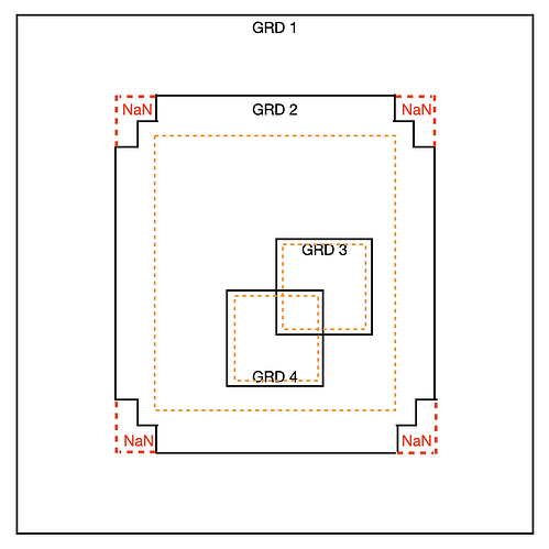
Is there a way to blend these 4 GRDs with cosine tapers?

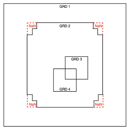
GRD3 is rectangular, but its corners are filled with NaNs and should be replaced with GRD4, but the cosine taper should also smoothly transition across the irregular corners of GRD3.

Also need a cosine taper between GRD1 and GRD2, and between each of those and GRD3.

Thank you,
Mike

Maybe. You indicate that there are NaNs in the corners of Grd3 but your drawing shows it for grid 2? Anyway, you can control the blending in two ways:

  • Specify an inner region per grid and that sets the cosine ramp between that region and the extent of the grid. The inner part of the region will get relative weights of 1 while nodes in the fringes will go from 1 to 0.
  • Give the different grid different absolute weights. These are then multiplied by the relative weights in the step above and the resulting modified weights are then used to compute the final weighted average at any point. Any NaNs are skipped entirely.

Looking at your drawing your final grid will be grd 1 out outside the grd2 border and it will taper into grd2 inside the inner region you select, and then the same happens with grd3 and grd4. If any of these data set are considered higher quality you would give those higher absolute weight. If the point at the center of the square that shows overlap of grd 3 and 4 is inside the inner regions of both grids (hence all relative weights are 1), then the output there would be the average of all four grids, unless you gave them different absolute weights, in which case the output would be bias toward the grids with the higher absolute weight.

Thanks for the reply. You are correct – that is a typo about the NaNs… GRD 2 has the NaNs in its corners, not GRD3.

First, let me ask a couple basic questions just to make sure I understand what the taper is doing…

In the grdblend documentation, it says, “…weights are [1] inside the given -R [grid domain] and cosine taper to 0 at actual grid -R.”

What is meant by “actual grid -R”? Is that an individual input grid’s -R or the -R specified for the final blended product?

Is the cosine taper circularly symmetric from an input grid’s center or does it work in X and Y independently?

OK, now back to the challenge at hand…

Another important requirement is the order of precedence, specifically, GRD4 >> GRD3 >> GRD2 >> GRD1 in order of precedence. So, for example, every output pixel where GRD 4 exists should be set to the GRD 4 value except in its transition region where the cosine taper applies. Similarly, every output pixel where only GRDs 1,2,3 exist should be set to GRD3 except in its transition region where the cosine taper applies.

I think this amounts to a combined clobber+taper mode: clobber in the inner regions according to the order of precedence and weighted average in the taper edge regions. Perhaps this can be done with the absolute weights as you suggest. To set each grid’s absolute weight, would I just use a number other than 1 for the 3rd column of the input file?

I’ve attached an updated figure showing the inner regions of GRDs 4,3,2 as orange dashed lines.

Then the input file should be something like:

GRD4 <GRD4 -R shrunk by a small amount> 1e6
GRD3 <GRD3 -R shrunk by a small amount> 1e4
GRD2 <GRD2 -R shrunk by a small amount> 1e2
GRD1 <GRD1 full -R> 1

Where all 4 exist, the output value will be approximately equal to GRD4 (since its weight is >> the others). Similarly, where only GRDs 1,2,3 exist, the output value will be approximately GRD3 since its weight is >> GRD 1 and 2’s.

But, at the corners of GRD2, will the cosine ramp correctly taper to 0 at the solid black line of GRD2 given the irregular distance to its dashed orange line?

Also, since the absolute weights are so different does that make the cosine taper more of a hard step function, thereby reducing its ability to smooth out any seams between the grids? For example, in the outer edge of GRD4 that overlaps with GRD2, the ramp has to go from 1e6 to 1e2 in a short distance.

It seems that I might have to strike a balance between the desire to reduce seams (requiring tapering with similar absolute weights between the grids) and the desire to do clobbering in the inner regions (requiring vastly different weights to achieve the desired order of precedence).

Thanks a lot for your help!

Mike
The tapering is applied in the region between each individual grids domain and an inner domain that you specify in the blend file. So for example, if a grid has domain 0/100/0/50 and you specify the inner domain as 10/90/10/40 then the relative weights computed for this grid will be 1 inside 10/90/10/40 and the product of wx * wy in the margins where xw and xy are cosine taper functions in x and y, respectively, that go from 0 at the grid domain limits to 1 at the inside domain boundaries. I think grdblend could need a figure to make this clear…

Yes, I think the more different the absolute weights you give in the blend files are then quicker the transition. You will have to experiment I think and control the ramping via absolute weights that are not magnitudes apart. Since it can be hard to look at the finished blended grid and see what actually happened, one option is to use grdmath to create new grids with the same extends but set them to the constants 1 2 3 4. Then blend and plot the resulting grid which should be 1 where grd1 dominates, ramp to 2 towards 2 etc etc.

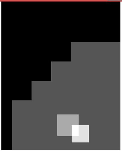
Ok, thanks for the tips! I tried a quick test along the lines of what you suggested by filling each grid with 1, 2, 3, or 4.

grdinfo -C grd?.grd

grd1.grd -110 0 0 140 1 1 0.05 0.05 2200 2800
grd2.grd -100 100 -100 100 2 2 0.05 0.05 4000 4000
grd3.grd -58.45 -38.55 13.05 32.95 3 3 0.05 0.05 398 398
grd4.grd -44.95 -29.05 7.05 22.95 4 4 0.05 0.05 318 318

I used the following input list:

grd4.grd -37.95/-36.05/14.05/15.95 1
grd3.grd -52.45/-44.55/19.05/26.95 1
grd2.grd -90/90/-90/90 1
grd1.grd -110/0/0/110 1

Except for grd1, the inner regions are all much smaller than the grid extents, so I would have expected to see the cosine taper for each grid in the blended result, but instead it looks like only a weighted average was applied: only 5 gray levels: 2.5, 2.33, 2, 1.5, 1.

The syntax for the region in the blend file is -Rw/e/s/n, not w/e/s/n. I fell into the same trap this morning which lead me to fix it. The version in the master GitHub repo now support just w/e/s/n but not in 6.3 of course.

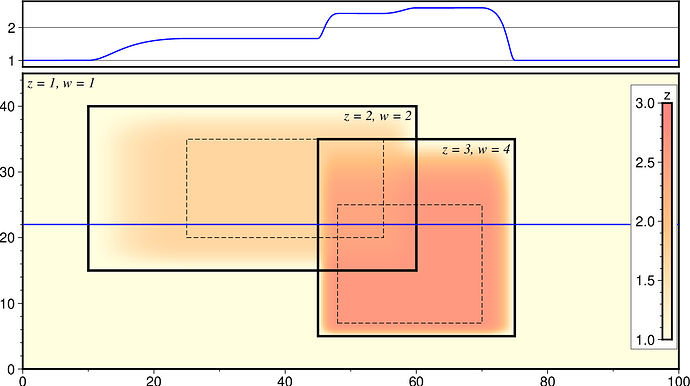
The updated grdblend man page shows this example with three grids, one with z = 1 (weight = 1), another with z = 2 (weight = 2) and a third with z = 3 (weight = 4). The image shows the blend and the crossection shows the tapering along that line.